
A sensor case in 217 lines of JavaScript
Three things on the desk. An nRF52840 Pro Micro board, 34 × 17 mm. A lithium cell, 12 × 30. A temperature, humidity and pressure sensor — a 15 × 15 square.
They need a box.
Not a pretty one, not one for the ages — one where the board doesn’t rattle, the USB-C reaches the cable, and the sensor measures the room rather than the warmth of its own battery. What follows is how that box is written in cadcode, all of it, from the measurements to two STLs on the print bed. The file is in the repository as examples/sensor-case.js, it is 217 lines long, and it drew every picture here itself.
Measurements first, shape second
Every case starts with the calipers. Whatever you measure goes straight into params:
export const params = {
  // Print
  wall: 2.0, // wall thickness
  floorT: 1.6, // floor
  lidT: 1.6, // lid
  fit: 0.15, // gap between the lid skirt and the wall, per side
  cornerR: 2.0, // outer corner radius

  // Pro Micro board
  boardL: 34,
  boardW: 17,
  boardT: 1.6,
  boardStandoff: 2.0, // board sits on rails, room for wires/pads underneath

  // Battery
  batD: 12,
  batL: 30,
  batClr: 0.5,

  // Sensor
  sensorS: 15,
  sensorPadH: 3, // tape pad, raised so air flows underneath
  sensL: 17, // sensor compartment length along X
  // ...
};
These are not just constants at the top of a file. They are the spec — and the knobs. Everything declared here can be overridden from the command line, and the same list turns into a panel in the preview. We’ll get to both.
The components come first, drawn as they are — blanks of the right size:
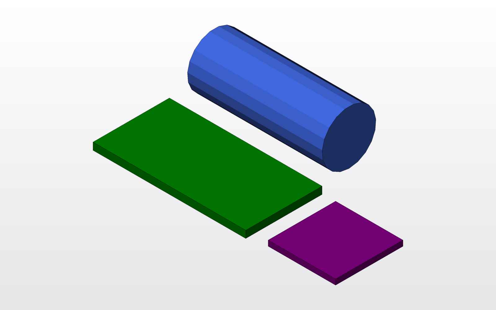
Three primitives, for now. But everything else is computed from them.
The inside is computed, not given
The outer size of the box is written nowhere. It follows from what has to fit inside:
const mainL = boardX0 + boardL + 0.7; // main compartment
const divT = 1.6; // divider between compartments
const batY0 = boardY0 + boardW + 1.5;
const iL = mainL + divT + sensL;
const iW = batY0 + batD + batClr + 1.0; // +1 mm: battery clears the lid skirt
const iH = batD + batClr + 0.5;
Two compartments: the board and the battery in the big one, the sensor in the small one, a divider between them. The length follows the board, the width follows the board and the battery side by side, the height follows the battery, the thickest thing in there. Take a fatter cell and the box gets wider and taller on its own — with the lid, the snap fit and the vents.
This is the whole reason to write CAD as code. A size that is derived cannot drift from what it was derived from. In a program you drive with a mouse that is called a “parametric model”, and it takes discipline. Here it is arithmetic.
To see the result, the program prints it:
console.log(`Outer size: ${iL + 2 * wall} x ${iW + 2 * wall} x ${iH + floorT + lidT} mm`);
Outer size: 57.6 x 36.5 x 16.2 mm
A rounded box is a hull of four cylinders
A box with rounded corners is the convex hull around four cylinders, one in each corner:
const roundedBox = (l, w, h, r) =>
  hull(product([r, l - r], [r, w - r]).map(([x, y]) => cylinder({ r, h }).translate([x, y, 0])));
product is OpenSCAD’s nested for: every pair of x and y, four corners. The case is that box minus its inside:
difference(
  roundedBox(iL + 2 * wall, iW + 2 * wall, iH + floorT, cornerR).translate([-wall, -wall, -floorT]),
  cube([iL, iW, iH + 1]),
  // ...
)
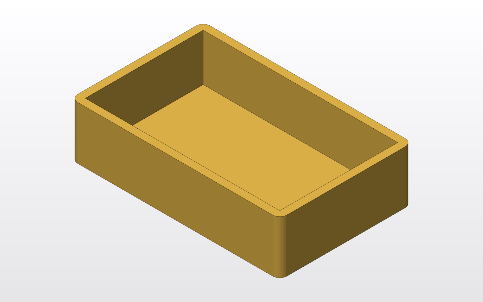
The inner cube is a millimetre taller than the box, so the subtraction is sure to cut through the top instead of leaving a skin of zero thickness. An old OpenSCAD habit, and it still earns its keep.
Mock-ups inside the box
Now the blanks go where they will sit, and get a colour each:
const dummies = () => [
  cube([boardL, boardW, boardT]).translate([boardX0, boardY0, boardStandoff]).color('green'),
  cube([7.5, usbW, usbH]).translate([boardX0 - 0.5, usbCy - usbW / 2, boardStandoff + boardT]).color('silver'),
  cylinder({ d: batD, h: batL })
    .rotate([0, 90, 0])
    .translate([mainL / 2 - batL / 2, batY0 + (batD + batClr) / 2, (batD + batClr) / 2])
    .color('royalblue'),
  cube([sensorS, sensorS, 1.2]).translate([sx0 + (sensL - sensorS) / 2, (iW - sensorS) / 2, sensorPadH]).color('purple'),
];
They never get printed. They are there to look at. In the assembly the case is see-through, the lid is lifted 8 mm and see-through too — and you can tell at once what touches and what rattles:
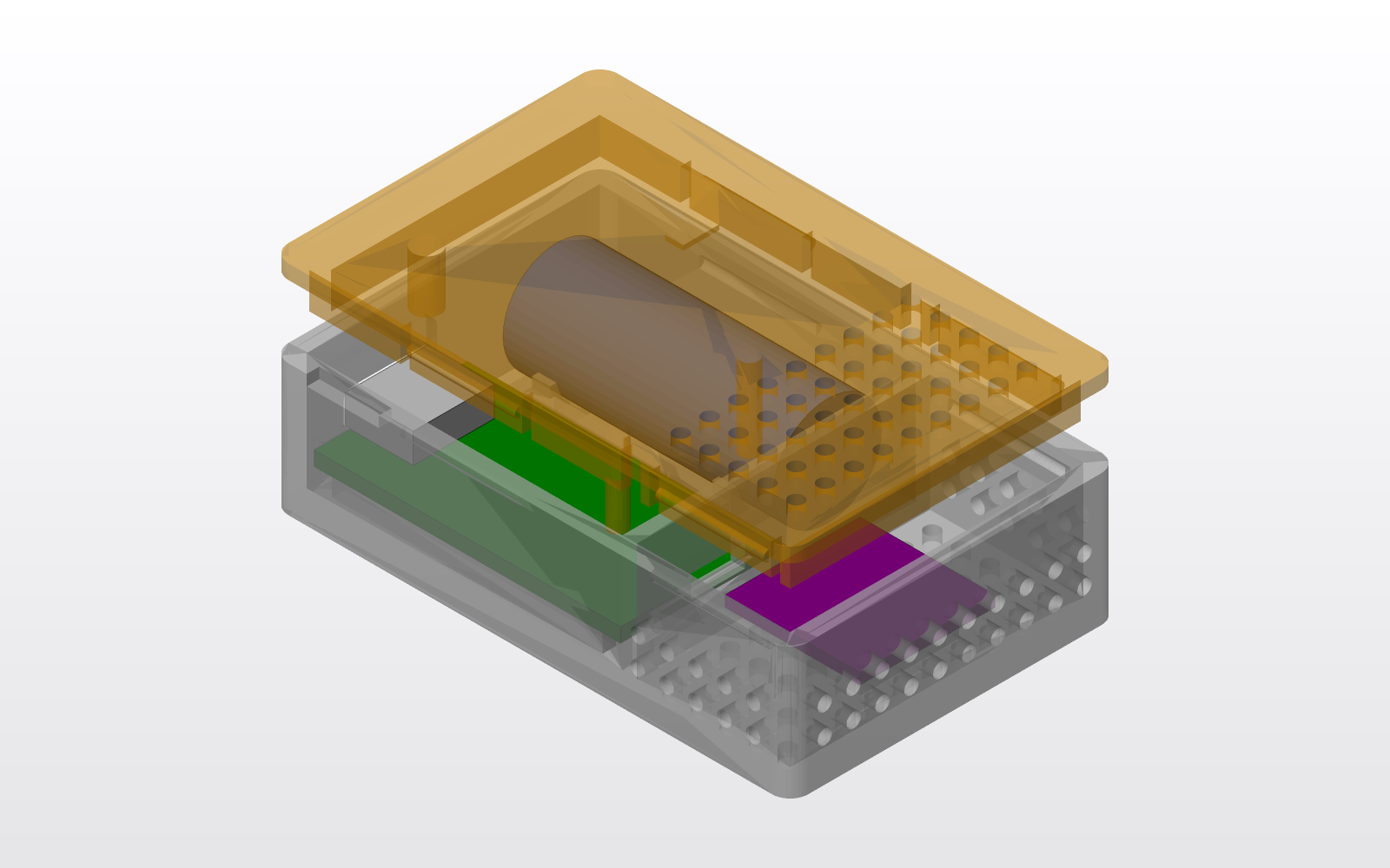
Every solid keeps its own colour and transparency, and they survive booleans. To the STL that means nothing — it merges everything into one body. To the eye it means everything.
The USB-C window is a 2D sketch
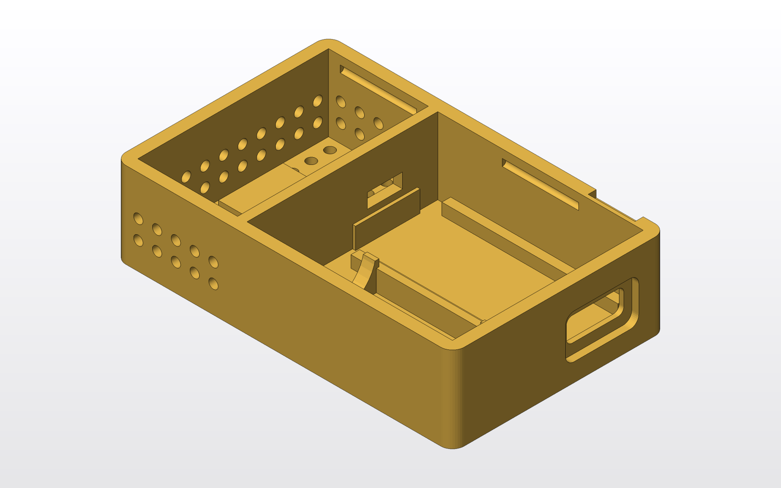
A USB-C plug is rounded, and the window for it should be too. The easy way is to draw it flat, round it, and only then extrude it:
// USB-C: through window + recess for the plug outside
square([usbH + usbSlotExtra - 2, usbW + usbSlotExtra - 2], { center: true })
  .offset(1)
  .extrude(wall + 2)
  .rotate([0, 90, 0])
  .translate([-wall - 1, usbCy, usbCz]),
square([plugH - 3, plugW - 3], { center: true })
  .offset(1.5)
  .extrude(plugDepth + 1)
  .rotate([0, 90, 0])
  .translate([-wall - 1, usbCy, usbCz]),
The square is 2 mm short, and offset(1) gives that size back, with the corners rounded. The second window is a shallow 1.2 mm recess for the plug’s plastic overmold, so it goes all the way in.
Read the chain top to bottom: sketch, round, extrude, turn onto the wall, move into place. In OpenSCAD the same thing would read bottom to top.
The lid holds on a snap fit
No screws. The lid drops a 4 mm skirt inside, the skirt carries ridges, and the case walls have grooves for them. The ridge and the groove are the same cylinder lying on its side:
const snapLine = (len) => cylinder({ r: bumpR, h: len, center: true }).rotate([0, 90, 0]);
The case subtracts it; the lid adds it, trimmed so only the outward half sticks out:
product(bumpXs, [fit, iW - fit]).map(([x, y]) =>
  intersection(
    snapLine(bumpLen).translate([x, y, iH - lipD / 2]),
    cube([iL, iW - 2 * fit + 2 * bumpR, iH]).translate([0, fit - bumpR, 0]),
  ),
),
A solid skirt would barely flex, so it has slits on either side of each ridge — that makes tabs. There is a notch in the skirt for the divider. Under the lid are three pins: one presses down on the USB-C connector, two on the far edge of the board. One more post holds the battery.
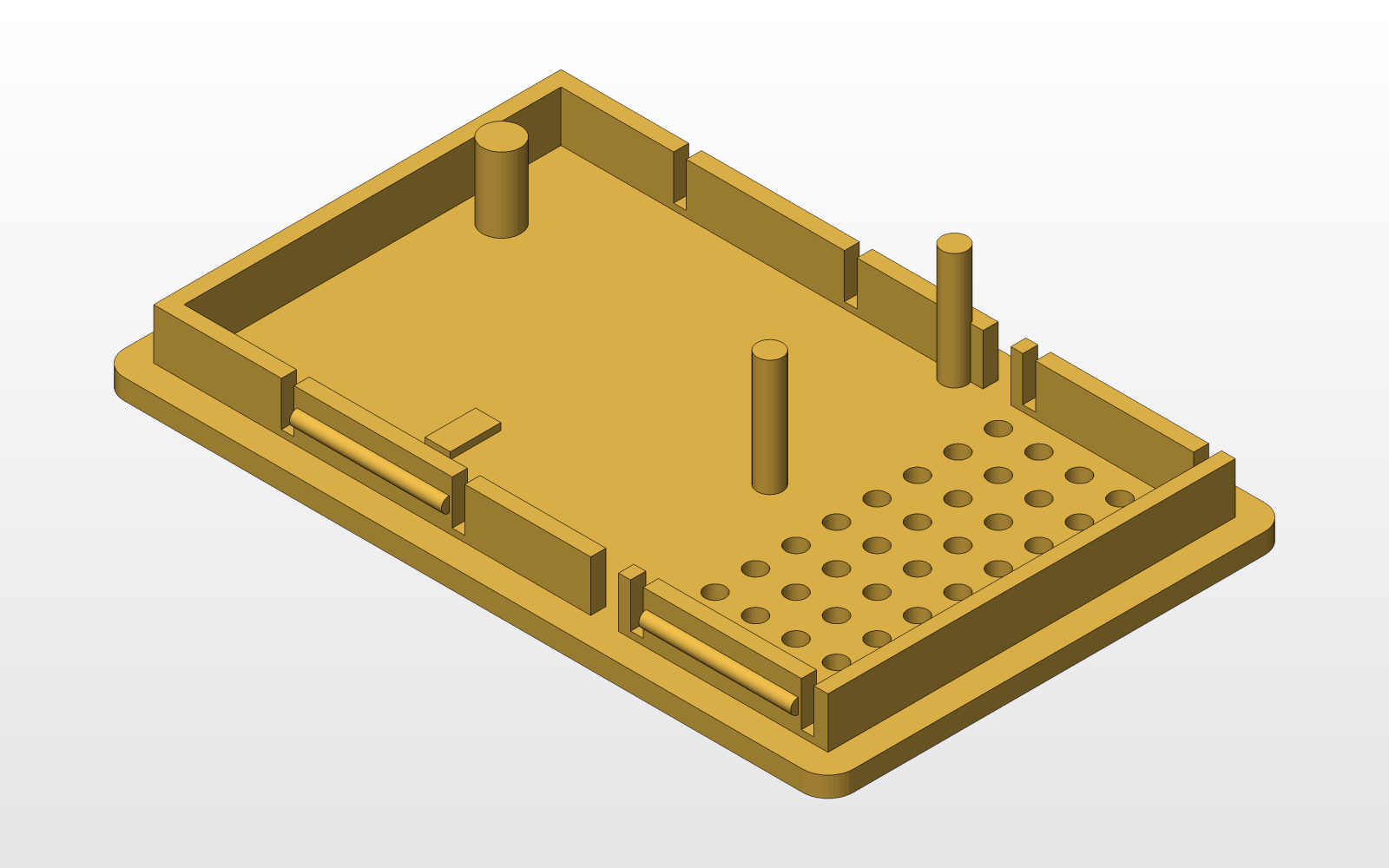
The gap between the skirt and the wall is that fit: 0.15 per side. Remember it.
The sensor needs air
A sensor in a closed box measures the box. So its compartment is full of holes: in the end wall, both side walls, the floor, and the lid above it. A hole grid is easiest described once — as a function of the size of the patch:
const poreGrid = (a, b) => {
  const na = Math.floor((a - poreD) / porePitch) + 1;
  const nb = Math.floor((b - poreD) / porePitch) + 1;
  const oa = (a - (na - 1) * porePitch) / 2;
  const ob = (b - (nb - 1) * porePitch) / 2;
  return union(
    product(range(0, na - 1), range(0, nb - 1)).map(([i, j]) =>
      cylinder({ d: poreD, h: 10, center: true }).translate([oa + i * porePitch, ob + j * porePitch, 0]),
    ),
  );
};
It works out how many holes fit at a 3.2 mm pitch, and centres the grid on the patch by itself. Then it is turned onto whichever wall needs it. Five places, one function.
The sensor itself doesn’t lie on the floor but on a 3 mm pad, so air passes underneath it too. The board sits on two 2 mm rails, which leaves room for wires below. The divider has a window for the I²C wires.
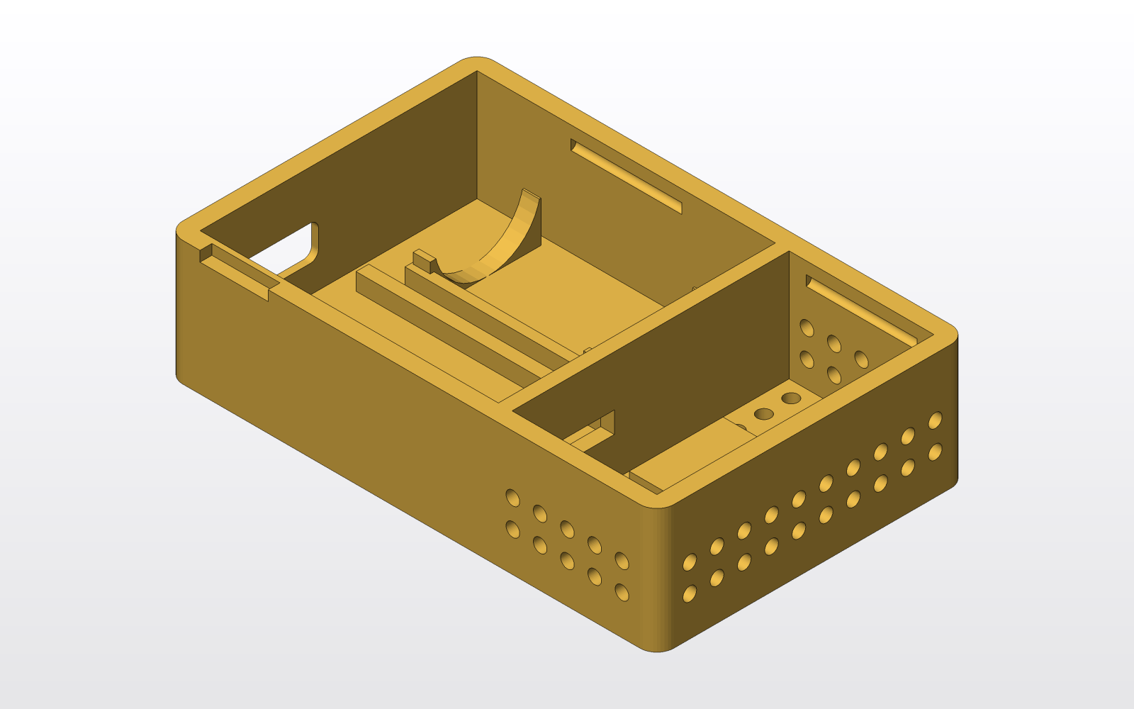
One last detail — a fingernail notch in the long wall. A snap fit that holds well opens badly.
Four parts from one file
The program returns not one solid but an object of named parts:
return {
  assembly: () => [box().color('lightgray', 0.5), lid().translate([0, 0, 8]).color('orange', 0.35), dummies()],
  box,
  lid: () => lidForPrint().translate([0, 0, iH + lidT]),
  print: () => [box(), lidForPrint().translate([0, iW + 2 * wall + 6, iH + lidT])],
};
assembly is for looking. box and lid are each on their own. print is both, the way they go on the bed: the case floor down, the lid flipped top down, so the skirt with its ridges prints without supports.
const lidForPrint = () => lid().translate([0, -iW, 0]).rotate([180, 0, 0]);
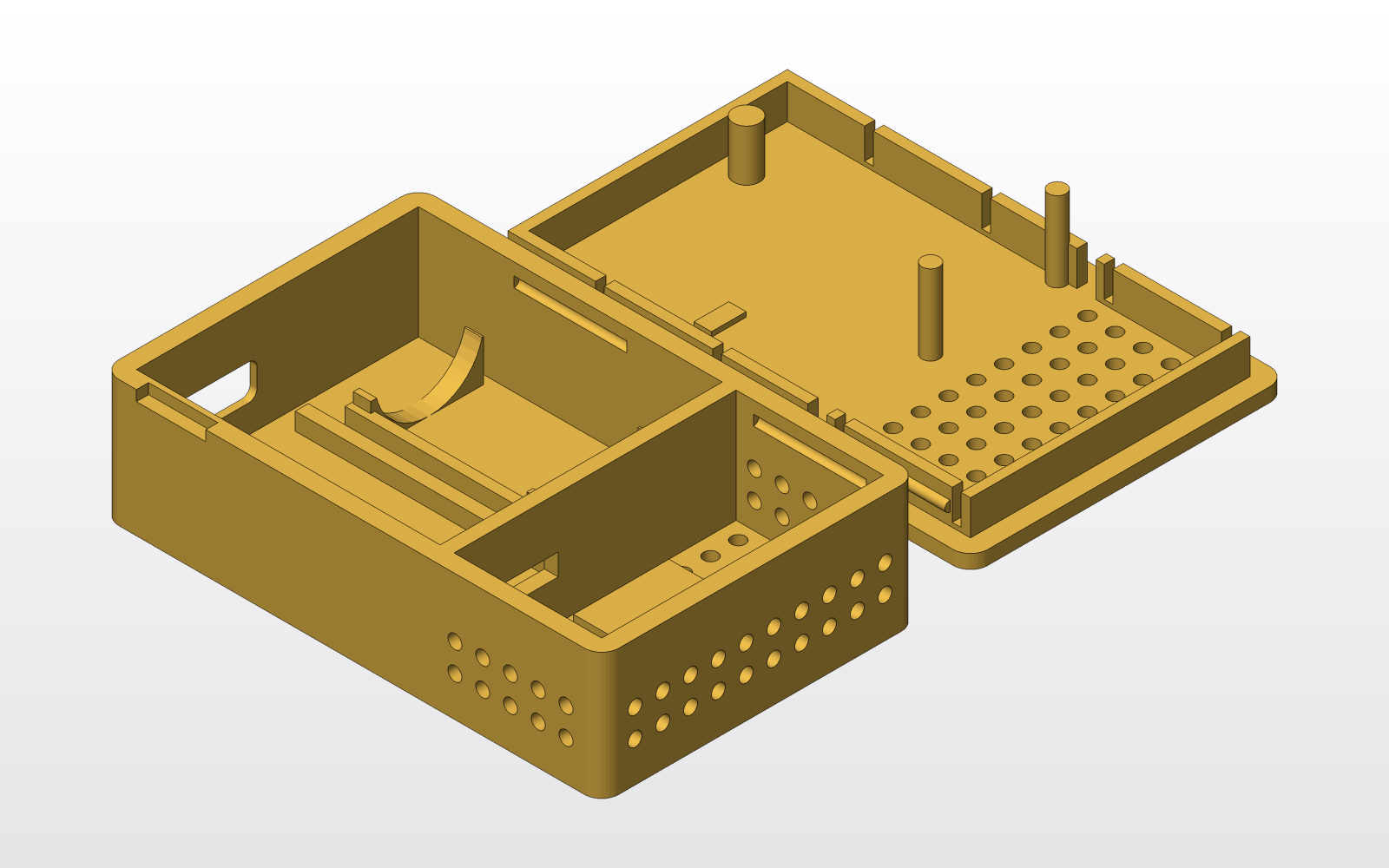
Parts are functions, and only the one being shown or exported gets called. The mock-ups are not computed when you print the case.
cadcode parts sensor-case.js
Outer size: 57.6 x 36.5 x 16.2 mm
assembly
box
lid
print
cadcode stl sensor-case.js --all -o out/
Outer size: 57.6 x 36.5 x 16.2 mm
assembly → out/sensor-case-assembly.stl (51 ms)
Outer size: 57.6 x 36.5 x 16.2 mm
box → out/sensor-case-box.stl (185 ms)
Outer size: 57.6 x 36.5 x 16.2 mm
lid → out/sensor-case-lid.stl (77 ms)
Outer size: 57.6 x 36.5 x 16.2 mm
print → out/sensor-case-print.stl (264 ms)
For checking by eye there is cadcode png — and the sheet view, an isometric plus three projections in one image:
cadcode png sensor-case.js --part assembly --view sheet --size 1600x1200
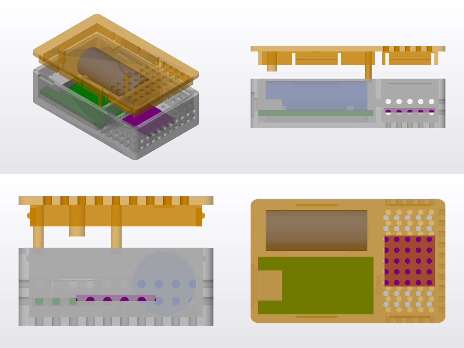
cadcode renders it itself, with no browser and no GPU. So the same sheet comes out of CI, or out of an agent that writes a part and wants to look at it.
The clearance is a flag
fit: 0.15 is a guess. How much you actually need is known only to your printer, your filament and your slicer. If the lid won’t go on, nothing needs redrawing:
cadcode stl sensor-case.js --part print --set fit=0.2
Outer size: 57.6 x 36.5 x 16.2 mm
print → sensor-case-print.stl (291 ms)
The skirt got narrower, and the ridges moved with it. Everything that depended on fit was recomputed.
A typo, meanwhile, does not slip through:
cadcode stl sensor-case.js --set fti=0.2
cadcode: Unknown parameter "fti". Declared: wall, floorT, lidT, fit, cornerR, boardL, boardW, boardT, boardStandoff, boardX0, boardY0, usbW, usbH, usbSlotExtra, plugW, plugH, plugDepth, batD, batL, batClr, sensorS, sensorPadH, sensL, lipD, lipT, bumpR, bumpLen, poreD, porePitch
Not “printed with the old value”. Not “ignored”. Refused.
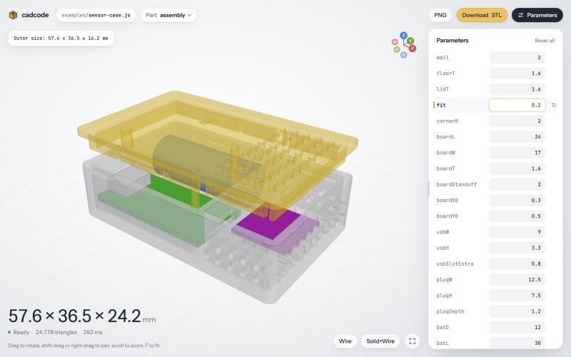
While you are tuning by eye, cadcode dev is the nicer place. It opens the model in the browser and rebuilds it on every save without moving the camera. The same params are a panel on the right: type a number, or drag its name sideways. A changed value is marked and resets on its own, and the Download STL button hands you the part with it applied. Whatever console.log printed sits in the corner.
Where that leaves us
Two hundred-odd lines. A third of them are measurements and comments you would have written down somewhere anyway. The rest are functions that describe not a shape but an intent: “a box around this”, “a grid of holes on that patch”, “a snap here and here”.
A different board is three different numbers in params.
Comments 0
No comments yet.